Digital Embroidery Patch
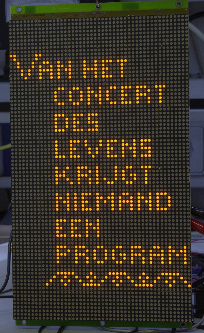
From my best friend, sadly deceased, I got a Surtronics 48x80 pixel LED display. This large (192x384 mm) display with 60 8x8 LED matrix modules was used in buses to show line number and destination. Now I could never find a purpose for this panel until I looked at my Grandma's embroidery patch:

It reads: "From the Concert of Life nobody gets a program". The stitches on the fabric reminded me of pixels and it (almost) fit the matrix panel:

So now I needed to fix the controller. This is a MACH211 which accepts serial data from a Toslink fiber. I don't know the protocol this chip expects but there are many initiatives to replace it with some other chip, like Atmel Duino. So I removed the MACH from the board and replaced it with an 18-pin socket for a PIC:
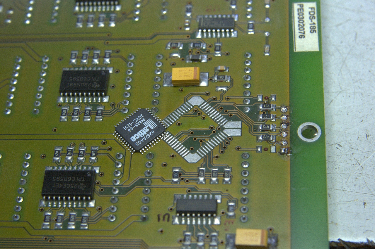
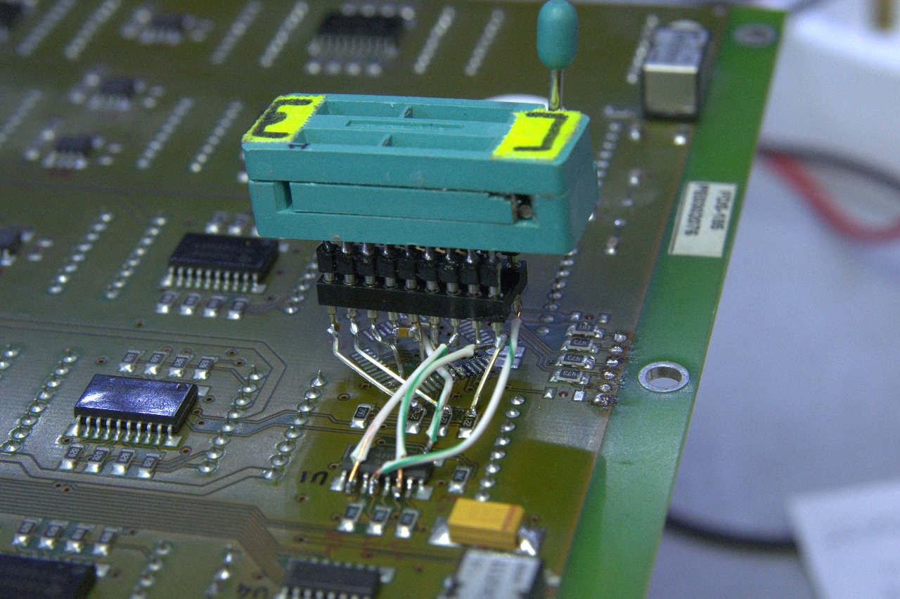
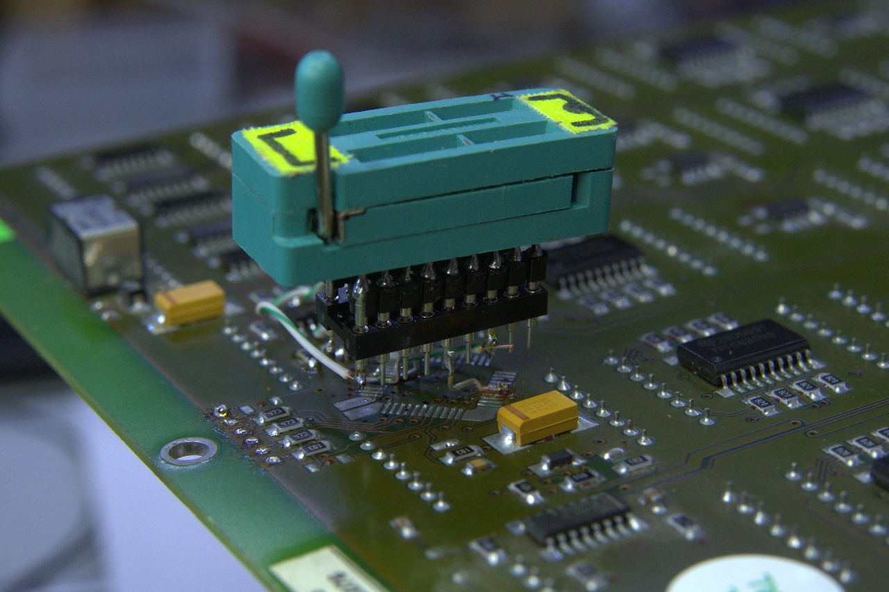
The optical receiver and transmitter can be seen above. The socket is hard to solder onto the narrow pitch pads but I succeeded. The ZIF socket was needed for testing the code and is now replaced by the PIC.
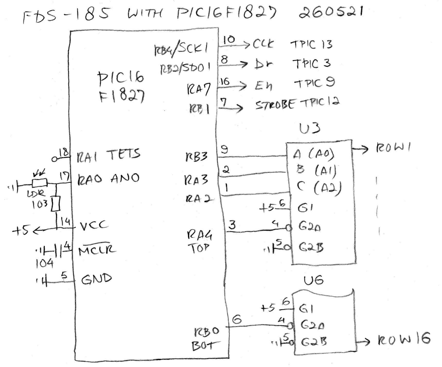
Now I had to write code. I had done this before, the display is just a very long shift register, but never this big. The FDS-185 matrix LED display (schematic is for the smaller FDS-184 with only 192 columns) is made up of 16 rows by 240 columns. The scanning starts from the bottom right to the top left in five blocks (click to embiggen):
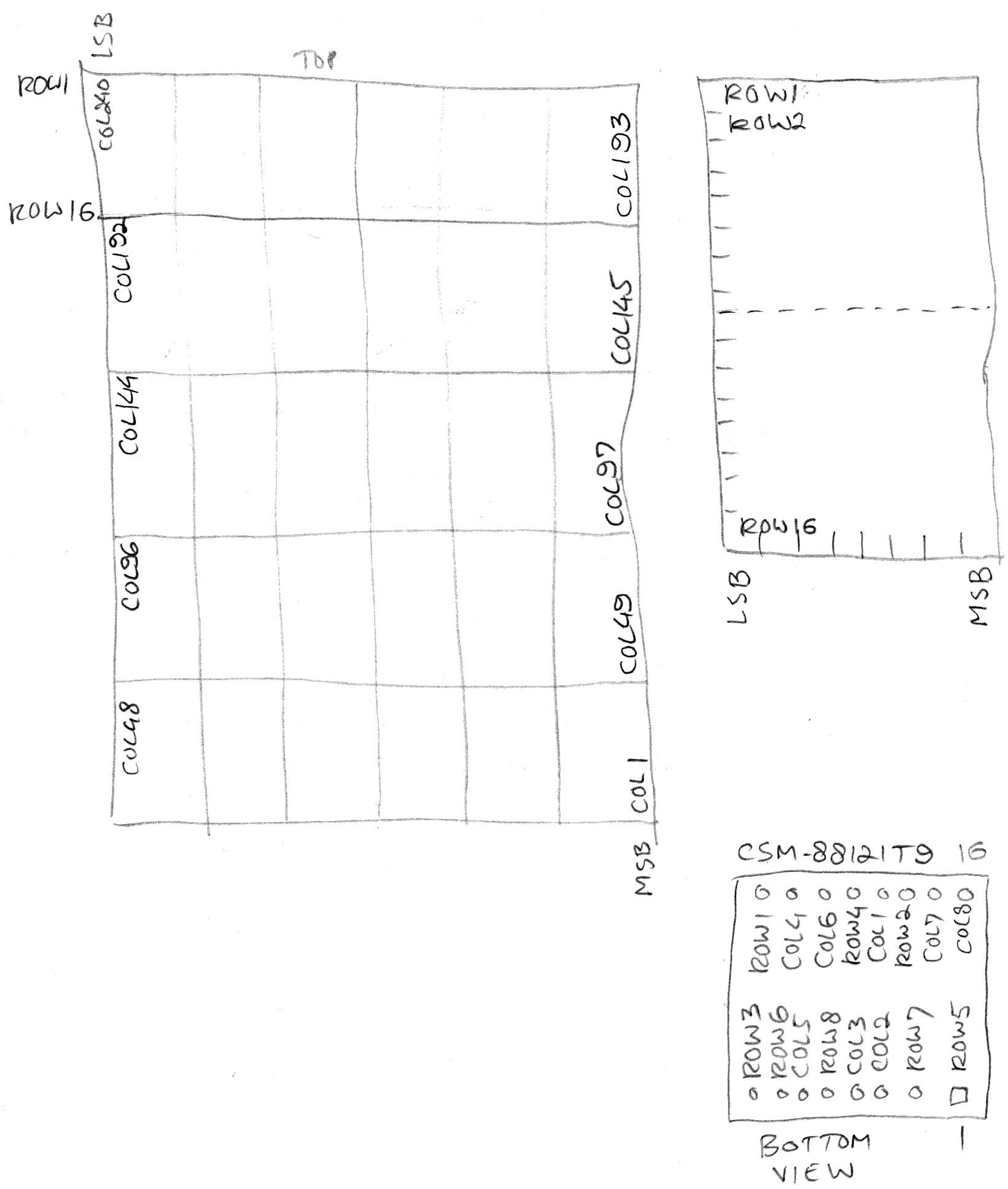
Once I figured out how to drive the display I had to get the pixel values from the digital rendering above. I cut it in five pieces and glued it together:

and then manually decode each row:
0x45
0x29
0x31
0x92
0x10
0x00
0x04
0xB5
0xEA
0x9A
0xD0
0x00
0x00
0x3A
0x3D
0x17
0x10
13x 0x00
After doing eight rows someone suggested to use the despised AI to perform this task and lo and behold, after some "thinking" it produced the correct table:
Row
00: 45 29 31 92 10 00 04 B5 EA 9A D0 00 00 3A 5D 17 10 00 00 00 00 00 00 00
00 00 00 00 00 00
Row 01: 00 00 00 00 00 00 04 A5 28 8A 90 00 00 0A C5 11 10 00 00 00 00 00
00 00 00 00 00 00 00 00
Row 02: 00 00 00 00 00 00 03 A5 28 BA 90 00 00 3B 4C A3 10 00 03 9D D9 26
60 00 00 00 00 00 00 00
Row 03: 1F 08 7C 21 F0 00 00 00 00 00 00 00 00 22 44 A1 10 00 01 24 45 69
10 00 00 00 00 00 00 00
Row 04: 24 94 92 52 48 00 00 00 00 00 00 00 00 3A 5C 47 70 00 01 1C C5 A9
10 00 00 00 00 00 00 00
Row 05: 4A 49 29 24 A4 00 00 00 00 97 70 00 00 00 00 00 00 00 01 24 45 29
10 00 00 00 00 00 00 00
Row 06: 84 3E 10 F8 42 00 00 00 00 B1 10 00 00 00 00 00 00 00 01 25 D9 26
60 00 00 00 00 00 00 00
Row 07: 00 00 00 00 00 00 00 00 00 D3 30 00 00 39 90 9C 90 00 00 00 00 00
00 00 00 00 00 00 00 00
Row 08: 00 00 00 00 00 00 00 00 00 91 10 00 00 10 50 A4 50 00 00 00 00 00
00 00 00 00 00 00 00 00
Row 09: 00 00 00 00 00 00 00 00 00 97 70 00 00 13 50 9C 70 00 00 00 00 EE
70 00 00 00 00 00 01 83
Row 10: 00 00 00 00 00 00 00 00 00 00 00 00 00 12 52 A4 90 00 00 00 00 22
90 00 00 00 00 00 00 82
Row 11: 00 00 00 00 00 00 00 00 00 00 00 00 00 11 8C A5 10 00 00 00 00 E6
90 00 00 00 EE 91 26 44
Row 12: 00 00 00 00 00 00 44 C7 31 8E 70 00 00 00 00 00 00 00 00 00 00 82
90 00 00 00 42 91 69 44
Row 13: 00 00 00 00 00 00 6D 29 0A 52 90 00 00 00 00 00 00 00 00 00 00 EE
70 00 00 00 46 F1 AF 28
Row 14: 00 00 00 00 00 00 55 E7 6A 4E 70 00 03 A4 C8 BA 90 00 00 00 00 00
00 00 00 00 42 91 29 28
Row 15: 00 00 00 00 00 00 45 29 4A 52 10 00 04 AD 2D 8A B0 00 00 00 00 00
00 00 00 00 4E 91 29 10
As it had taken me 38 minutes to do the first eight rows AI saved me about half an hour because I had to write the prompt and then upload the image. But still.
Now I had the correct data it was time to include it in the bitbanger. I had chosen the PIC16F1827 because of its high clock frequency of 32 MHz, its easy lookup table adressing and the RWM issue workaround (port latches). One of the issues I had to solve once I got the data on the display is the ghosting that appeared:
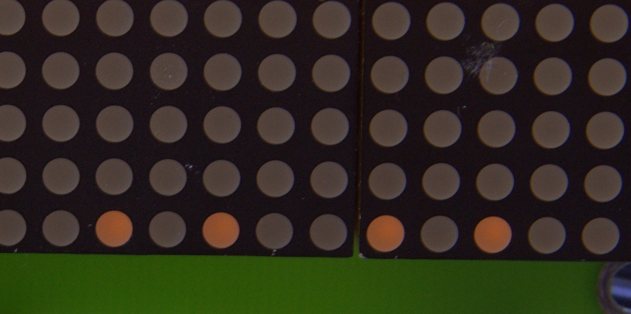
This is simply caused by the shift register data still present while the next row is switched on. Luckily the TPIC6B595, like any shift register, has an output enable pin which can be used to switch off the columns. I took the opportunity to include a brightness control based on an LDR to adjust to ambient lighting. This works by switching off the columns, switch to the next row and then only switch them back on after the brightness set point has been reached. This is the subroutine GETBRT.
Another issue was that the image data is too large to fit in a single 256-byte page. So I had to cut the lookup table in half (ROWDATA1 and -2). Easy peasy. The hardware now looks like this:
Now I had the program completed (.asm) I could enjoy the image:
Back to the projects page
Date: 10 June 2026

This software is licensed under the CC-GNU
GPL.