LM35 PWM Phan Controller
A friend of mine came to me with an interesting design challenge: a fan controller for a water cooling system in his gaming rig. Its mobo (mother board) supports this, as do specialized applications. The problem with either is that when they crash the fans go phut and the system could overheat. That actually happened and he asked for a standalone PWM fan controller. I came up with a controller (schematic) with an LED readout and two buttons to change its settings.
Quickly I kludged together some code only to find out that it was buggy. Many iterations later I had finally fixed the PIC program.
The premise is simple: Output a PWM signal for a fan whose duty cycle is calculated from a temperature threshold and a slope. The slope is a factor with which the PWM is multiplied as the temperature rises, the threshold is the temperature above which that happens. The two buttons double as function select and up/down adjust. When both are pressed simultaneously it shows the PWM value as debug feature. The PWM is specified with a minimum duty cycle of a 20 kHz square wave. The mobo should have the fan supply voltage fixed on +12 V. The controller forwards the fan's tacho signal on to the mobo. The controller also needs to know the temperature of the cooling system. For that an LM35 temperature sensor is used. Its output is digitized by the PIC's analog to digital converter (ADC) and used to calculate the PWM duty cycle. The minimum as specified in Intel's specification is 15%.
When the power is applied the PWM ramps up to 100% and then back to 15%. After a quick lamp test the display shows:
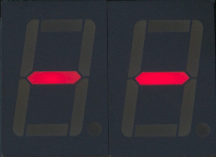
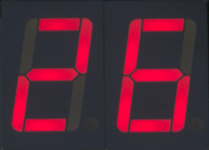
Once this is done the temperature (in degrees Celcius) shows:
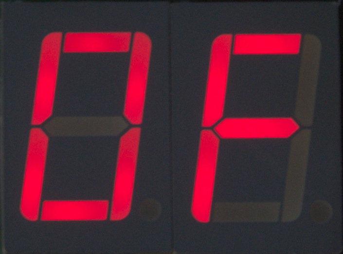
To check the PWM value (in hex), press both buttons simultaneously:
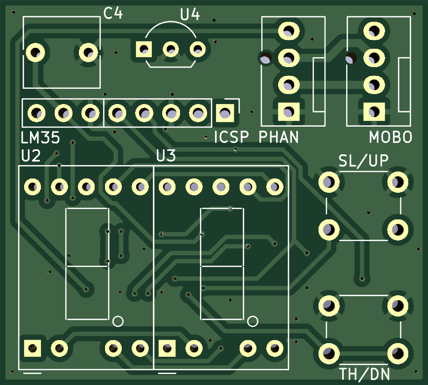
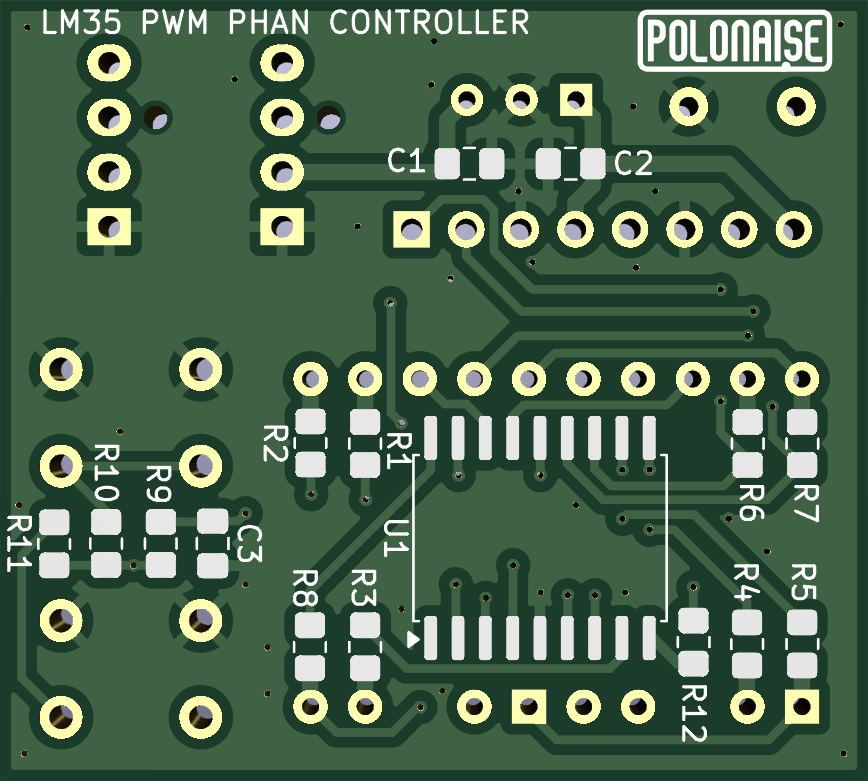
The controller is built on a small PCB:
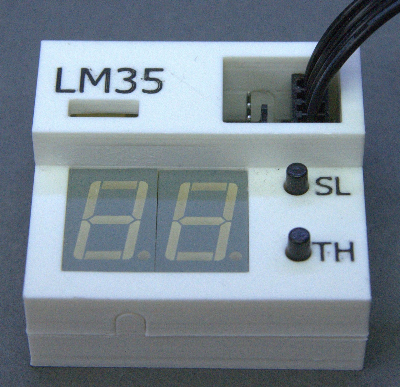
Finally, a nice boxie was 3D printed:
Back to the projects page
Date: 30 July 2026

This software is licensed under the CC-GNU
GPL.